Driving loads by phase angle and pulse train
Power controllers or power modules are devices used to control the amount of energy applied to the load of several processes. The amount of energy to be applied (load) is defined by the process controller, which then passes the information to the power controller via the output signal.
The power controller controls the thyristors, internal components that have a high capacity to conduct electricity. These, in turn, act as electrical switches and, as such, are devices that have only two states: On or off. How, then, can the process load be delivered in energy quantities other than 0 % (thyristor off) or 100 % (thyristor on)?
The answer can be found in the technique used to modulate the mains voltage supplying the load. By switching the thyristors on and off at particular times, it is possible to obtain average power values that are proportional to those set by the process controller.
Two techniques are traditionally used:
1 – Voltage modulation by phase angle
Each AC mains cycle is divided into two half-cycles. These semi-cycles are divided into degrees, a total of 180 degrees for each semi-cycle.
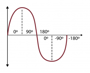
In phase angle modulation, the thyristors are switched on every half-cycle of the mains. Modulation occurs by switching on the thyristor at the angle that corresponds to the percentage of electrical power defined by the input signal of the power controller. And it will be switched off the next time it crosses zero. Only part of each half-cycle is transferred to the load.
For example: For a power of 50 %, set by the input signal, the thyristor switches on at 90° and off at 180° (when crossing zero). See the graph below:
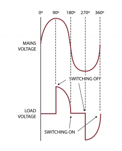
Below are other power values applied to the load:
This type of modulation allows you to obtain more refined control over the process. Low values in the input signal produce low voltage values on the load. This feature is important in processes where it is necessary to limit the electric current in the first moments after the process is switched on. The example shows the type of drive recommended to be installed on the primary side of transformers. To avoid problems when switching off the load, it is not recommended to use electrical power values lower than 25 % in these applications.
2 – Voltage modulation by integral cycle (equivalent to pulse train)
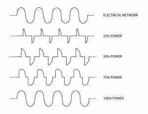
In this type of modulation, it is possible to control electrical power by reducing the number of network cycles applied to the load. The power controller establishes the number of grid cycles to be transferred to the load. For example: For 10 % power (set by the input signal), the power controller applies 1 cycle to the load every 10 mains cycles. For 25 %, it applies 1 cycle every 4. For 50 %, it applies 1 every 2. See the graph below:
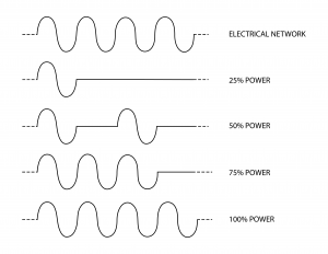
Thus, the load is switched on when the mains voltage crosses zero and switched off when the electric current of the load crosses zero. This feature brings important advantages to the installation, as no noise is produced.
Another important advantage of this type of modulation is the possibility of achieving a more linear drive of the load. As this technique does not require a cycle time, the load does not have to be activated for long periods.
For example: In a pulse train modulation with a cycle period set at 1 second, when the power controller applies 25 % power to the load, the load remains on for 0.25 seconds and off for 0.75 seconds. This way, you get a sort of “beat”. Under these conditions, incandescent light bulbs would continue to blink. With the technique without the cycle period, the load switches on for 16.6 ms (1 cycle) and remains off for another 49.8 ms (3 main cycles).
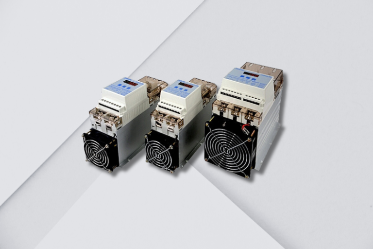
PCW and PCWE power controllers
In NOVUS’ PCW and PCWE power controllers, you can find 2 techniques for driving electrical loads in the same device. When configuring the controller, you can select which technique to use. In addition to this advantage, NOVUS’ controllers have the following features:
- Load voltage: 180~440 Vac; 50/60 Hz
- Control signal: 0-20 mA, 4-20 mA, 0-5 V, 1-5 V, 0-10 V, 2-10 V and 10 k potentiometer
- Control power supply: 220 Vac; 50/60 Hz
- Alarm with SPST relay; 3 A / 250 Vac
- Dielectric strength between parts: 2500 V
- Operating temperature: -10 to 60 °C
- Plastic housing: ABS+PC / UL-94V0
- For 220/380 V networks
- Housing compatible with NR10 standards
- Pulse train and phase angle in one model
- Multiple control signals
- Built-in fuses
Read more:
NOVUS SSR line is certified by Underwriters Laboratories Temperature and humidity monitoring with NOVUS devices helps to preserve the artistic heritage of Rio Grande do Sul How to choose a process controller for your application