Applications to measure temperature with signal conditioners
Temperature is one of the most commonly measured quantities in industry. It is essential to measure and monitor temperature to guarantee the quality, safety, and proper operation of several processes. To obtain these results, you must consider several factors when developing a temperature measurement system.
Good examples involve the non-linearity of sensors or the accuracy and stability needed to ensure greater reliability. Other variables, such as maintenance and wiring costs, must also be considered to optimize the cost-effectiveness of the solution.
Over the years, many temperature measurement systems have been developed by good experts. However, there are still doubts when it comes to deciding which sensor to use in an application. Choosing between connecting the sensor directly to the control equipment or using a temperature transmitter to measure and transmit the signal is also a frequent concern.
Here we explain some basic concepts about temperature and the variables to consider, allowing you to choose the best option.
Temperature Sensors
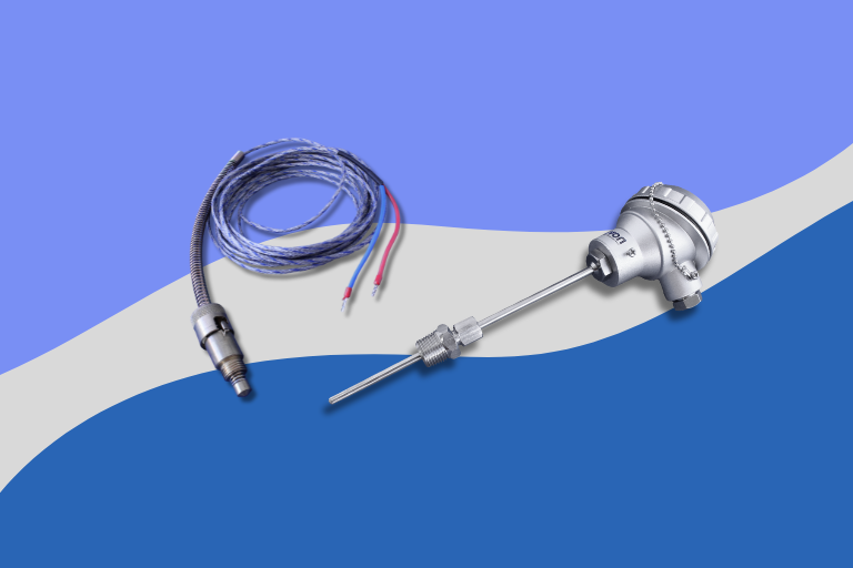
Resistance thermometers and thermocouples are the most common sensors in industry. It’s important to identify them to compare them.
-
Resistance thermometers
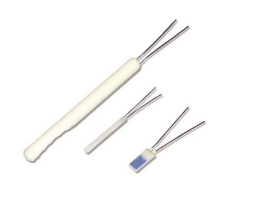 Basically, a resistance thermometer is a resistor that varies its resistance according to the temperature to which it is exposed. This resistance can be measured to determine the temperature of the element.
The most commonly used resistance thermometers in industry are made of platinum. The most well-known are the Pt100 and Pt1000, but there are others. Resistance thermometers are fragile and sensitive to vibration. They are usually encapsulated to achieve greater mechanical resistance. They offer greater precision and guarantee more consistent results when compared to thermocouples, so they are widely used whenever a more reliable measurement is required.
-
Thermocouples
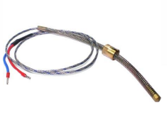 Thermocouples are composed of two metallic conductors which are joined at one end. This creates a junction known as a hot junction. Whenever the temperature changes, a potential difference will be measured between the two conductors at the other end. This is known as a cold junction. This potential difference (measured in millivolts) is measured and interpreted according to the conductors used when manufacturing the sensor. The result obtained with the linearizations and compensations is the hot junction temperature of the thermocouple.
Several types of thermocouples are available on the market. Types K, J, E, T, and N are the most common, since they are cheaper when compared to thermocouples made of noble metals (such as types B, R, and S, used in more specific and usually high-temperature applications).
Thermocouples are ideal for high-temperature applications. They are usually cheaper than resistance thermometers and can be made in smaller buildings. They also respond more quickly to temperature changes and are more durable when exposed to vibration and shocks.
Direct connection or measurement through transmitters?
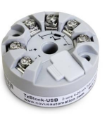
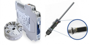
Normally, when developing a temperature measurement system, you must consider two possibilities. One involves connecting the sensor directly to a measuring instrument. The other involves using a temperature transmitter to convert the sensor signal into a more robust signal, such as a current signal (4-20 mA), for example.
Some field engineers mistakenly believe that connecting the sensor directly to an equipment reduces costs and has no impact on measurement quality. However, there are reasons to consider other variables when deciding between the direct connection or the connection with transmitters.
Reducing wiring costs
When the signal from a thermocouple must be measured away from the hot junction, it must be carried through extension or compensating cables to ensure reliability. Extension or compensating cables are expensive and often too fragile. A pair of these special cables can cost 5 to 10 times more than a pair of copper wires of the same length. Thus, the economy increases proportionally to the signal transmission distance.
When measuring a four-wire resistance thermometer with a temperature transmitter, you will need only one pair of wires to transmit the signal over long distances (and not four wires, as in the direct measurement process). Furthermore, since the resistance of resistance thermometers varies according to temperature, the impact on the quality of the measurement increases as the length of the sensor cable increases, due to the electrical resistance of the conductor. Temperature transmitters usually use an algorithm to compensate for the electrical resistance of the conductors.
Saving money when investing in the system
Most of the devices on the market can measure standard analog signals in current and/or voltage. Expansion modules capable of reading specific sensors are widely available but are expensive. Apart from the high cost, a system using an expansion module would also require the sensor to be connected directly to the module, which is not recommended for all the reasons already mentioned in this article.
Protecting the measurement from external noise
Due to their low amplitude, signals from thermocouples and resistance thermometers are susceptible to noise in factory plants. Electromagnetic interference is present in virtually every industrial environment and can affect the measured signal when using a direct connection between the sensor and the measuring equipment. Transmitters are subjected to electromagnetic compatibility tests to ensure that they can eliminate interference that could affect the measured signal.
Maintenance and commissioning
Temperature transmitters can be configured more quickly and conveniently, and it is also easier to carry out the diagnostic process. With these features, the field engineer can troubleshoot a temperature measurement system in much more efficient ways. In addition, when the sensor has a malfunction or connection problem, the temperature transmitters generate specific output signals. Several transmitters are offered with specific protocols such as HART®, IO-Link®, or even a USB configuration port.
Flexibility when choosing a sensor
Temperature transmitters usually have a universal input, which means they can be configured to read a wide variety of temperature sensors. This eases the process of replacing a sensor and ultimately reduces the inventory levels of distributors and integrators.
If you need to change the system’s measurement range, for example, the sensor can be replaced, and the transmitter can be simply reconfigured to cover the new range.
Avoiding ground loops
 Ground loops are a common cause of noise and interference in temperature measurement systems. A ground loop occurs when two grounded points on the same circuit have different potentials. This effect is normally observed in applications where the thermocouple is grounded, a situation which requires a fast response to temperature variation.
You can avoid ground loops by using isolated temperature transmitters. This specific type of transmitter has galvanic isolation between the sensor input and the analog output. This isolation prevents current from circulating between the two sides of the circuit and eliminates ground loops.
Abstract
Nowadays, using transmitters in temperature measurement systems is becoming increasingly common and, in some cases, mandatory. These devices, which have different types of assembly, are highly cost-effective solutions thanks to the latest microprocessor technologies. The benefits are not just related to cost savings, but to efficiency gains in maintenance, cabling, diagnostics, and better measurement quality.
Read more:
How to avoid and fix ground loop problems