PID Control tuning
The control literature presents several techniques for tuning, both operating the process in manual (open loop) and automatic (closed loop) mode. It is beyond the scope of this article to present these techniques. The vast majority of industrial PID controllers has “Auto Tune” features, where the controller applies a test to the process and obtains the PID parameter set (Pb, Ir, and Dt).
>>>> This article builds on what was presented here: The basics of PID Control
For most processes, this calculation is adequate. In many cases, it is necessary to perform a manual adjustment to achieve a more satisfactory control performance (less overshoot, faster stabilization, etc.).
To perform this adjustment manually, it is essential to understand the operating principles explained here. The following are guidelines for manually optimizing the performance of a PID controller.
Manually correcting PID
In many cases, it is necessary to perform tuning adjustment after the Auto Tune has been completed. This tuning is manual and should be done by trial and error, applying a change to the PID parameters and checking the performance of the process until the desired performance is obtained. This requires knowledge of the effect of each PID parameter on control performance and experience with different processes.
Definitions of good control performance are also quite varied. Many times, the user expects from his system a response that it is not able to achieve, regardless of the controller used. It is common for the operator to complain that the furnace temperature takes too long to rise but the controller is always at 100 % MV, i.e., there is nothing else to do to speed up.
Sometimes the operator also wants speed but does not want overshoot, often conflicting desires.
When evaluating the controller performance, it is important to analyze the behavior of PV and MV and verify that the controller is acting on MV at the appropriate times. Put yourself in the shoes of the controller and imagine what you would do with the MV and compare it to the action taken by the controller. As experience is gained, this kind of judgment becomes very effective.
Table 2 below summarizes the effect of each parameter on process performance:
| PARAMETER | BY INCREASING, THE PROCESS … | BY DECREASING, THE PROCESS … |
Pb |
It gets slower.
It generally gets more stable or less oscillating. It has less overshoot. |
It gets faster.
It gets more unstable or more oscillating. It has more overshoot. |
Ir |
It gets faster, reaching the Setpoint quickly.
It gets more unstable or more oscillating. It has more overshoot. |
It gets slower, taking longer to reach the Setpoint.
It gets more stable or more oscillating. It has less overshoot. |
| Dt | It gets slower.
It has less overshoot. |
It gets faster.
It has more overshoot. |
Table 2 – The effect of each PID parameter on the process
Table 3 below presents suggestions to change the PID parameters based on the process behavior to improve it:
| IF THE PROCESS PERFORMANCE … | TRY THE OPTIONS ONE BY ONE: |
| It is almost good but the overshoot is a little high. | Increase Pb by 20 %.
Decrease Ir by 20 %. Increase Dt by 50 %. |
| It is almost good but there is no overshoot, and it takes a while to reach the Setpoint. | Decrease Pb by 20 %.
Increase Ir by 20 %. Decrease Dt by 50 %. |
| It is good, but MV is always varying between 0 % and 100 % or is varying too much. | Decrease Dt by 50 %.
Increase Pb by 20 %. |
| It is bad. After startup, the transient has several periods of oscillation, which reduces very slowly or not at all. | Increase Pb by 50 %. |
| It is bad. After startup, it moves slowly towards the Setpoint, without overshoot. It is still far from the Setpoint and MV is already less than 100 %. | Decrease Pb by 50 %.
Increase Ir by 50 %. Decrease Dt by 70 %. |
Table 3 – How to improve process performance
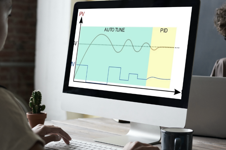
Figure 4 shows the behavior of PV during Auto Tuning of a process that had to oscillate 2.5 cycles to obtain the measurements needed to calculate the PID parameters:

Figure 4 – Test applied to the process during Auto Tuning
Self-adaptive tuning in NOVUS Controllers
The most advanced NOVUS controllers have Self-Adaptive Tuning functions in addition to the Auto Tuning feature. When enabled by the user, the Self-Adaptive Tuning function continuously monitors the performance of the PID control loop and makes a new adjustment to the Pb, Ir, and Dt parameters whenever performance worsens from earlier observations.
The Self-Adaptive Tuning technique of the NOVUS controllers is explained below.
How Self-Adaptive Tuning works
Self-Adaptive Tuning is a function of the controller that can be enabled or disabled by the user. Once this function is enabled and has been executed at least once, the controller continuously monitors the stability of PV and MV by calculating their variances. From the individual variances of PV and MV and reference values established for them after the previous tuning cycle, a performance index is calculated. It indicates whether a new adjustment of the control parameters is necessary.
If the process performance index is low, the controller automatically initiates an Auto Tuning cycle, applying small jumps in MV, without deteriorating the performance further, until it acquires information about the PV and MV behavior that allows it to recalculate the Pb, Ir and Dt parameters. Using these new parameters, the controller resumes PID control and establishes a new performance index to use as a reference.
Figure 5 shows the block diagram of the PID control system, performance monitor, and Auto Tuning:

Figure 5 – Block diagram of the Self-Adaptive PID control system
Figure 6 shows the behavior of PV and MV in a process that starts stable, degrades its performance, is automatically tuned to adjust the parameters Pb, Ir, and Dt to the new conditions, and returns to stability by PID control:

Figure 6 – PV and MV behavior in Self-Adaptive Tuning
Keep reading:
Meet the world’s first modular controller: N20K48
How to choose a process controller for your application
Get to know the differences between N1050 and N480D controllers